With the 5.1 Helion release, we introduced a new capability for architecture plugins that enables function-level basic block analysis by overriding the default implementation. This feature provides powerful new flexibility for performing control-flow recovery on architectures where instruction-level or even basic block-level analysis alone is inadequate for building an accurate control flow graph (CFG). In this post, we demonstrate how this mechanism can be leveraged to resolve zero-overhead hardware loops and accurately identify branch targets in parallel instruction pipelines.
Motivation
Digital Signal Processor (DSP) architectures often feature complex control flow mechanisms that present unique challenges for static analysis. For example, many DSPs implement zero-overhead loops where the loop control is managed by special hardware features rather than explicit branch instructions. This can lead to situations where the control flow graph (CFG) does not accurately reflect the intended execution path, especially when relying solely on instruction-level analysis. Likewise parallel instruction pipelines can complicate the identification of branch targets, as multiple instructions can execute simultaneously, leading to potential misinterpretation of control flow.
Consider this code example for Microchip PIC32, which features zero-overhead loops:
0x0039C   do #16383,0x03a2
0x0039E   nop
0x003A0   inc.w 0x000c
0x003A2   nop
The do instruction repeats a set of instructions n+1 times, where n is specified as a 14-bit constant or the lower
14 bits of any W register. In the code above, the do instruction stores the loop start address (the address of the
next instruction - 0x39e) in the DOSTART register and the loop end address (0x3a2) in the DOEND register. It
also sets the DOCOUNT register to 16383. Instructions from 0x39e through 0x3a2 are repeated until the DOCOUNT
register reaches zero.
By default, Binary Ninja’s core analysis engine invokes the architecture plugin’s get_instruction_info callback on
each instruction to determine its properties, such as whether the instruction includes branches. In the case of the
do assembly code above, get_instruction_info would be invoked on the nop instruction at 0x3a2, which is not a
branch instruction. As a result, the core analysis engine would not recognize the loop structure, leading to an
incomplete or incorrect CFG.
Parallel instruction pipelines can also complicate control flow analysis. For example, consider the following assembly code snippet from Qualcomm Hexagon architecture:
{
  if (p0) jump:nt 0x5b08;
  jump 0x5b7c;
  p0 = cmp.eq(r9,#9);
  r9 = add(r9, #1);
}
Hexagon packets can contain up to four instructions that execute in parallel. Hexagon also supports
dot-new predicates,
where the processor can generate and use a scalar predicate in the same instruction packet. In the example
above, the instruction packet contains a conditional branch that depends on the value of p0.new, which is set by the
cmp.eq instruction. If the p0.new predicate is true, the processor will jump to 0x5b08; otherwise, it will branch
to 0x5b7c. r9 is incremented by 1 prior to the branch. Processing this packet an instruction at a time would lead
to an incorrect interpretation of the control flow. It would result in the block ending at the first branch
instruction. A new block would be created on the next instruction, which jumps past the cmp.eq and add
instructions, causing code to be missed. In Hexagon, only one branch is taken per packet. If more than one branch is
eligible, the branch in the lowest execution slot number is taken.
Function-level Basic Block Analysis
In Binary Ninja 5.1, we introduced a new callback in the architecture class
(analyze_basic_blocks)
that allows plugins to implement a custom algorithm for performing function basic block analysis. This callback can be
used in lieu of
get_instruction_info
(or alongside it) to perform basic block analysis at the function level, rather than the instruction level.
To demonstrate this capability, I have updated my personal Brain***k architecture
plugin to use the new analyze_basic_blocks API to build an accurate control flow graph, eliminating a hack that was
previously required to handle loop structures.
Brain***k Overview
Brain***k (BF) is one of the most famous (infamous, even?) esoteric programming languages of all time. TL;DR - here’s a simple Hello World program:
>+++++++++[<++++++++>-]<.>++++++[<+++++>-]<-.+++++++..+++.>>
+++++++[<++++++>-]<++.------------.<++++++++.--------.+++.------.--------.
>+.>++++++++++.
Each character in the program is an instruction that operates on a memory tape, which is an array of memory cells, each initially set to zero. The pointer starts at the first cell and can be moved left or right. The description for each instruction is listed in the table below.
| Instruction | Description |
|---|---|
| > | Move the pointer to the right |
| < | Move the pointer to the left |
| + | Increment the memory cell at the pointer |
| - | Decrement the memory cell at the pointer |
| . | Output the character signified by the cell at the pointer |
| , | Input a character and store it in the cell at the pointer |
| [ | Jump past the matching ] if the cell at the pointer is 0 |
| ] | Jump back to the matching [ if the cell at the pointer is nonzero |
Brain***k Basic Block Analysis
The BF [ and ] instructions are used to represent the start and end of loops. Conceptually, BF loops are similar to
zero-overhead loops in DSPs, where the loop control is managed by the interpreter (or hardware) rather than explicit
branch instructions. A [ instruction caches the loop start address. When the ] instruction is encountered, the
interpreter checks the value of the current memory cell. If it is zero, the interpreter jumps to the instruction after
the matching ]. If it is nonzero, the interpreter jumps back to the matching [. To resolve the matching [ and
build an accurate control flow graph, instruction-level analysis is insufficient. We need contextual information about
the entire function to connect the outgoing edge of the block that ends with a [ instruction to the incoming edge of
the block with the matching ].
To implement this, I’ve overridden Binja’s default basic block analysis algorithm by implementing the
analyze_basic_blocks callback in the BF architecture plugin. The implementation is
straightforward. It iterates
through the instructions in the function and populates the function’s basic block list. When it encounters a [
instruction, it creates a new block and caches the loop start address. When it encounters a ], it ends the current
block and connects an outgoing edge with a “true branch” type to the block with the matching [ instruction, and a
“false branch” type to the next instruction by calling add_pending_outgoing_edge. Once the function basic block list
is fully populated, the BasicBlockAnalysisContext.finalize method is called to commit the basic block list to the
analysis. Here’s the result:
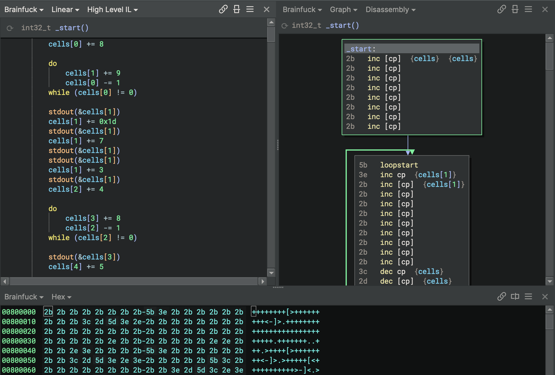
As you can see, the control flow graph is able to model the loop and connect the edges correctly, even though there is not an explicit branch instruction that specifies the branch target at the end of the loop.
A More Practical Example
Qualcomm Hexagon packets can contain up to four instructions that execute in parallel. Each instruction contains a 2 bit field that is used by the CPU to determine whether or not the instruction is the last in a packet. The parse bits across all instructions in a packet are used to encode the end of hardware loops. The parse fields in the first and second instructions of a packet encode whether or not the packet is the last packet in a hardware loop.
Instruction-level analysis is insufficient for determining the end of hardware loops, as detecting a loop packet requires examining the parse fields of multiple instructions in the packet. Hypothetically, a Hexagon hardware loop might look something like this in Binja:
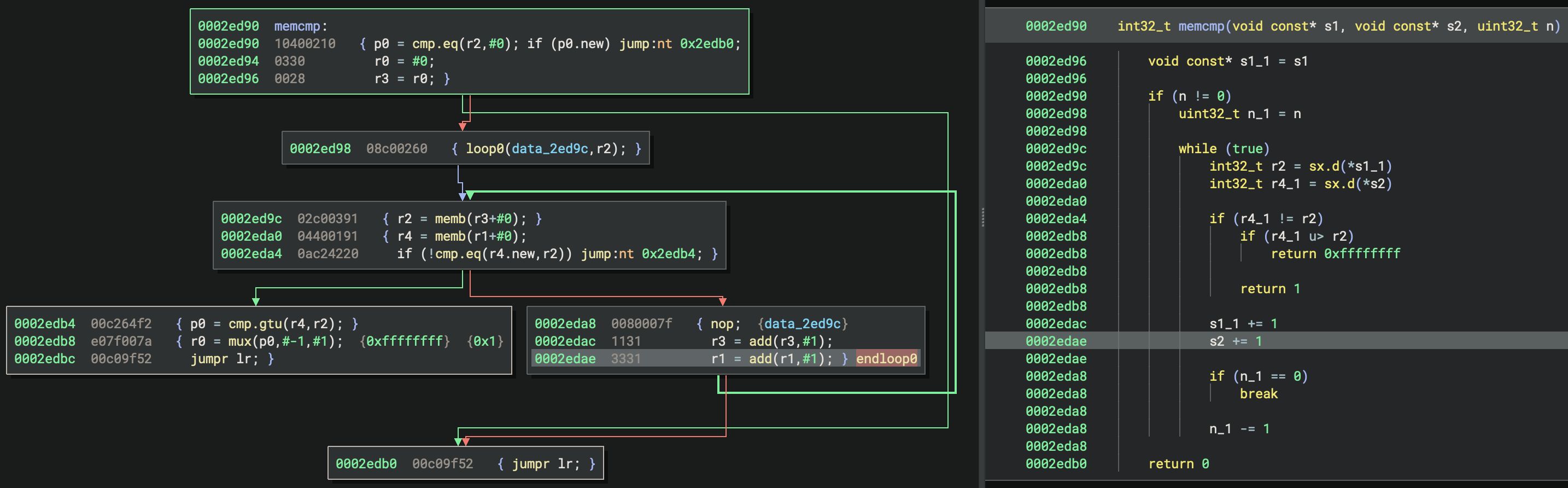
The instruction at 0x2ed98 sets the start of hardware loop 0 to 0x2ed9c and number of iterations to the value in
the r2 register. The packet at 0x2eda8 is a loop packet containing a nop instruction and a duplex instruction
consisting of two add instructions. By combining the packet’s opcode bytes, grouping them into 4-byte little-endian
words, and examining the parse fields, we can determine that the parse field for the first instruction is 10 and the
parse field for the second instruction is 00 signifying that it is a duplex instruction, which ends the packet. By
referencing the table below, we can see that the sequence of 10 00 indicates that this packet is the end of loop 0.
Our custom basic block analysis implementation for Hexagon leverages this information to accurately identify and
connect the block containing loop packet to the block at the start of the loop, resulting in a complete and accurate
control flow graph.
| Packet | Parse field in first instruction | Parse field in second instruction |
|---|---|---|
| Not last in loop | 01 or 11 | 01 or 11 |
| Last in loop 0 | 10 | 01, 11, or 00 |
| Last in loop 1 | 01 | 10 or 00 |
| Last in loops 0 & 1 | 10 | 10 or 00 |
What’s next?
The new function-level basic block analysis capability in Binary Ninja 5.1 provides a powerful mechanism for modeling complex control flow semantics in architectures where instruction-level analysis is insufficient. Not only does this feature enable the development of new architecture plugins for multiple DSPs, it can also be leveraged for basic block recovery in VM-based architectures such as WebAssembly, eBPF, and more which contain metadata sections that must be processed for accurate control flow recovery. We have started using this capability ourselves, and are excited to see how it is used by the community! Let us know if you’ve got any questions or feedback.